Since I've noticed a lot of interest in microprocessors here, I thought it was time someone put up a simple tutorial on microprocessor design. I don't claim to be anything even remotely resembling an expert on the subject, but I think I have enough knowledge to demonstrate the basic design principles.
To get started, you first need an electronics simulator. I recommend
Logisim for a simple free program. However, I will not be using Logisim in these tutorials because I'm not as familiar with it and to encourage understanding of the fundamental concepts rather than the simulator. The principles and circuits will be identical, though. Also, some of the images are mine, some are from Wikipedia and other sources. Citations are not included because the circuits themselves are not copyrighted content.
The first thing to understand when designing your own microprocessor is that you're not going to be making the next Intel i7 chip clocking 2.25 GHz on your first attempt. Commercial microprocessors often rely on advanced hardware optimizations and design principles that are beyond the scope of anything short of a graduate level design course. After you accept that, processor design isn't quite the black magic it's often portrayed to be. Like programming, it's mostly a matter of understanding the interactions between different subsections of the hardware.
Logic gatesThe most basic components of all of the electronic circuits we will be dealing with are logic gates. Logic gates are basically devices which produce outputs that are a logical function of their inputs. There are seven types of logic gates, each represented by the symbol next to it.
| AND |  |
| OR |  |
| NOT |  |
| NAND |  |
| NOR |  |
| Exclusive OR (XOR) |  |
| Exclusive NOR (XNOR) |  |
The inputs to logic gates take the physical form of voltage levels, most commonly 0 V and +5 V (other values can be used but the exact values aren't important). By convention, these voltage levels are referred to as representing the binary values 0 and 1 respectively. The logic gates operate on these inputs according to their
Truth tables. When the input combination matches an input combination on the left hand side of the corresponding table, the output is the same as that which appears on the right hand side of the table. For example, when the input to a NOT gate is 1 (+5 V), the output of the NOT gate is 0 (0 V).
CircuitsLogic gates are by themselves interesting, but there's no logic gate that implements say, a Z80 processor. This is because processors are composed of a lot of individual logic gates working together to accomplish the tasks required. So, let's start designing some small circuits that can do more than our individual logic gates.
1-2 Multiplexer (MUX): This device takes 2 data lines and an address line and places the value of of the data line whose address is equal to that of the address line on the output line.

2-1 Demultiplexer (DeMUX): This performs the inverse operation to a MUX. It takes one data line as well as an address line as inputs and places the value of the data line on the output line whose value is equal to the value on the address line.

Half adder: The half adder circuit takes two binary inputs and performs a binary addition on them. This produces two outputs, a sum and a carry-out.

Full adder: A full adder does the same thing as a half adder except that it also adds a carry-in bit to the operands.

There are many other types of circuits, but these simple ones will eventually form the basis of our microprocessor.
Basic MemoryAs any search through an electronics forum will reveal, memory is one of the most important parts of a computer. Like any important material, there are also a billion ways to accomplish its function. The most common are through what are known as flip-flops and latches (which are essentially the same thing). The most basic memory cell is known as an SR NOR latch and the circuit diagram is this:

While this looks simple, it has a few fundamental flaws. For one thing, the set and reset inputs are on two different lines. That's not ideal, since we will almost certainly be wanting to store data from a single line at some point. Secondly, what happens if both the set and reset lines are active at the same time? Does it set or reset? Well, we don't know. This is an example of a "Race condition" and it's a very bad thing to happen to a memory circuit. The cell goes into a state of indeterminacy and we have no way of predicting what the final state will be.
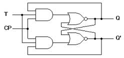
So, let's look at something else called the synchronous J-K flip-flop:
The J-K Flip-flop avoids the disastrous race condition from the SR latch, but it still has those two annoying set and reset lines. As it turns out, if you replace the first level NAND gates with AND gates and the second level NAND gates with NORs, you end up with something called a T flip-flop (where T stands for Toggle...).
The T flip-flop is definitely a step in the right direction, since we have only 1 data line (and a control line), but what if we don't want to toggle the bits every time the data line is active? In that case, you must go with something called a D flip-flop. D latches are the most commonly used type of solid state memory in existence today and will likely form the basis for most of our processor's memory.

The D latch is perfect for most purposes you will ever come across, but it turns out that you can optimize in many circumstances.
The truth tables for each of these circuits can be found
here.
The ALUAt this point, we have every circuit we need to build a computer that can perform any computation we wish. For the sake of simplicity, however, let's limit ourselves to something more reasonable: a four bit microprocessor.
One of the most important parts of any processor is the Arithmetic Logic unit, or the ALU. The function of the ALU is basically to perform all of the arithmetic and logical operations within the processor. As you can imagine, processors like the Intel i7 with floating point trigonometric instructions have extremely complex and powerful ALU's. Since we don't have supercomputers to generate our circuit diagrams, we'll go for something easier to draw and understand. Before we can begin designing it, though, we need to know what it will have to do. In keeping with a simple design, we'll limit it to addition, subtraction, AND, OR, NOT, XOR, NOP and logical bitshifts. This might seem limited, but it's actually all you need to have a fully functional computer (although technically we could reduce the instruction set even further without reducing power). One thing that some people may notice is that addition and subtraction can be combined into one operation through the use of what's called Two's complement notation. While this is certainly possible for us, it would require that we dedicate one bit to be the sign bit. That's 25% of our operands dedicated exclusively to sign. Since the processor uses so few bits, we'll instead use dedicated circuits for addition and subtraction.
Next: Putting it all together
